

Robotic Press Brake Cells: 기술, 장점 & Applications in Sheet Metal Fabrication
By Author: 마크 행크스
소개
Robotic press brake cells are a notable example of integration and innovation in metal fabrication technology. After cutting, press brake bending is one of the most widely used forming processes in the industry. There are many variables that affect the quality of forming with the press brake such as the material's tensile strength, 판 두께, bending design, and the gravity of the workpiece.
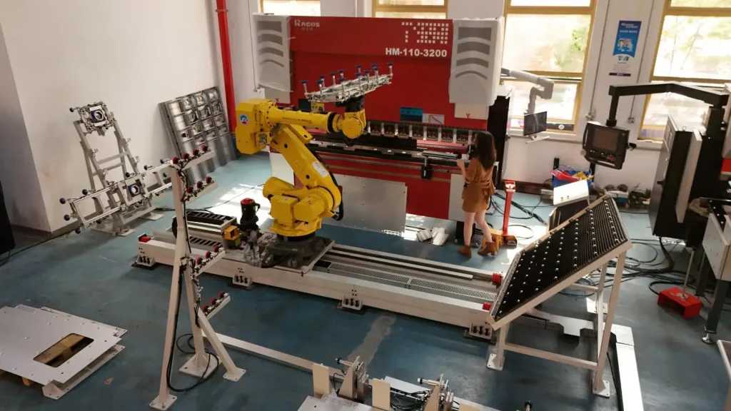
굽히는 과정 중, robotic gripper system is fundamental to the process of workpiece handling. Tooling for complex geometries and heavy workpieces requires frequent changes, and inaccuracies in tooling and a lack of flexibility for mixed production can pose serious challenges to manufacturers.
Robotic press brake cells provide an intelligent manufacturing system by integrating industrial robots, CNC 프레스 브레이크, automatic tooling with production control software. With the advent of smart technology and advanced industrial communications, manual press brake operations are gradually being replaced with automated, 지능, and data-focused production.
Why Are More Manufacturers Choosing Robotic Press Brake Cells?
Driven by Industry 4.0 and the shift toward smart manufacturing, modern fabricators are facing severe challenges: skyrocketing costs (both labor and raw materials), shortage of skilled operators, serious price competition, and growing demands for high-precision, low-volume custom parts with tight lead times.
To be competitive, manufacturers are turning to robotic bending automation to replace or reduce manual labor. Key automated solutions shaping the industry today include:
- Robotic Press Brake Cell Automation : Fully automated systems handling material loading, 하역, part positioning, 스태킹, as well as automatic tool and gripper changes.
- Production Line Automation: Teach-free programming
이 글에서, we describe a Supervisor + Modbus control-system architecture for robotic bending, wherein centralized control coordinates robotic systems, press brake CNC systems, and auxiliary support systems.
1.Robotic Bending Technology Overview
Among fabrication processes, bending is one of the most basic. Robotic press brake cells, such as those designed by JS Ragos, integrate digital manufacturing systems with industrial robotics, press brake technology, and software controls.
Thanks to PC-based controls, fieldbus technology, 그리고 지능형 소프트웨어, robotic bending systems turn the tacit knowledge of operators into programmable production information. Control algorithms and sensors offer the ability to monitor the positioning of workpieces in real-time, as well as control operating conditions and the accuracy of the bending process.
The integration of robotics with automatic loading, 위치, part identification, data acquisition, compensation control, and unloading systems transforms the bending process into a closed-loop production system with real-time data communication along the process (그림 1).
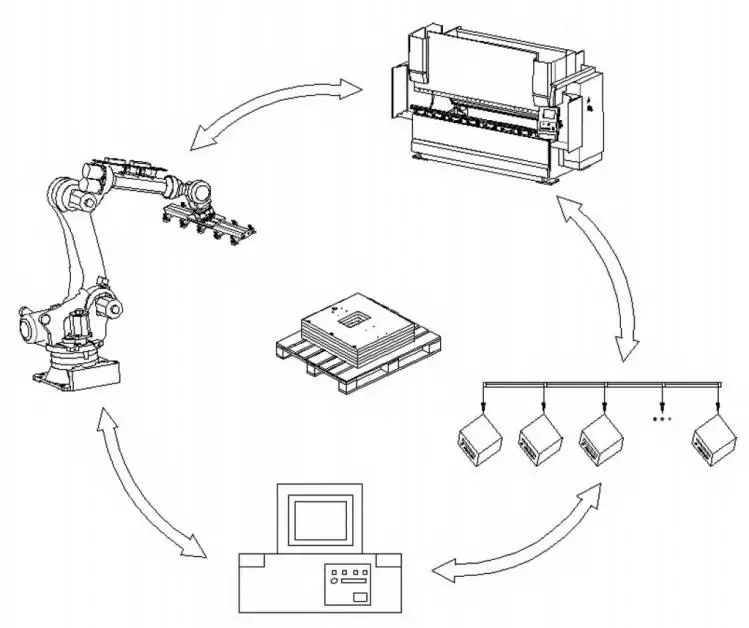
그림 1: Real-Time Data Sharing and Information Exchange Diagram
The robot performs:
• Workpiece gripping and positioning
• Part identification
• Inspection feedback
• Dynamic compensation
• Accuracy control
Current developments focus on flexible automation technologies, 포함:
• Single-sheet detection systems
• Pre-alignment tables
• Automatic flipping mechanisms
• Sensor-based edge detection and bend tracking
These technologies help robotic press brake cells move from single-product automation toward flexible intelligent manufacturing.
How Does a Robotic Press Brake Cell Work?
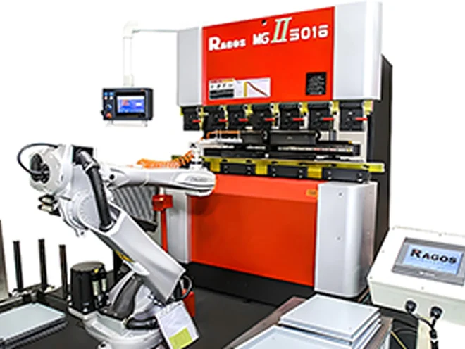
A robotic press brake cell uses advanced control software to combine an industrial robot, CNC 프레스 브레이크, and auxiliary systems to fully automate the bending of sheet metal.
Unlike conventional manual bending, a robotic press brake cell can perform the entire production sequence—from workpiece identification, automatic picking, and precise positioning to bending, part reorientation, and finished-part unloading.
A complete robotic press brake cell typically includes the following components:
CNC 프레스 브레이크
Industrial Robot
Robotic Gripper System
Automatic Tooling System
Sheet Positioning System
Control and Production Management Software
These systems exchange data through I/O interfaces and JS Ragos' offline programming software, allowing the robot, 프레스 브레이크, and auxiliary equipment to operate in a coordinated production process.
For buyers evaluating a complete system, explore the available robotic press brake cell configurations from JS RAGOS.
1. Production Program Preparation
Prior to production, the system generates the necessary machining program based on the workpiece 3D model and the associated material and bending requirements.
Using offline programming software or a production management system, engineers have the ability to determine:
Bending order
Selection of tools
Paths of robot movement
Methods of positioning the workpiece
The programmed data is subsequently sent to the robot controller and CNC press brake, thereby readying the cell for automated production.
As opposed to traditional manual teaching of robots, the JS Ragos' offline programming software for systems offers a substantial reduction in the time required for the initial setup, and an increase in the efficiency of the setup for varying production runs.
2. Automatic Workpiece Loading, Unloading, and Positioning
Upon commencement of production, the robot removes a unprocessed sheet metal part from a storage rack, pallet, or conveyor transport.
The correct gripper is determined based on the workpiece's dimensions, 무게, 기하학, 그리고 자료.
The gripper may be one of the following:
Vacuum gripper
Magnetic gripper
Pneumatic gripper
Hybrid gripper
In order to ensure the sheet is precisely positioned at the press brake centerline and backgauge, the robot corrects the orientation of the workpiece at a positioning station or a gripping station prior to entering the bending area.
3. Automated Bending Process
The robot then places the workpiece in the CNC press brake and instructs the machine to execute the bending process.
While in the bending phase, the robot is required to control:
The position of the workpiece
The applied gripping force
Rotation and/or flipping of the part
The planned path of motion
The required distance from the tools and equipment
The required safety distance
For more complicated 3D parts, including multi-bend parts, box-like structures, 인클로저, and large panels, the robot is able to automatically adjust its orientation and the position of its gripper for each of the bending operations.
In comparison to a manual press brake operation, a robotic press brake cell is able to achieve a higher level of consistency in the paths of motion, placement, and accuracy over the course of a given production cycle.
4. Automatic Tool and Gripper Management
In a high-mix production system, the varying product workpieces frequently necessitate the use of different press brake tools and associated robotic grippers.
A robotic press brake cell can incorporate:
Systems for automatic tool changing
Systems for automatic gripper changing
Metalix teach-free offline programming software
The combination of these technologies enables more rapid production changes for different workpieces.
Once the production task is modified, the system automatically adjusts to the desired configuration of tools and grippers, the bending program, and the associated paths for the robots. This is accomplished with limited manual intervention for setup and significantly minimizes the time required for task changing.
How a Robotic Bending Cell Functions
A bending cell combines several advanced technologies to perform automated sheet metal bending. Robotic bending cells typically consist of a manufacturing robot, a CNC press brake, auxiliary modules, and advanced control software.
Compared to conventional, manual sheet metal bending, a robotic cell is capable of fully automated production. This includes the identification, pick, placement, 굽히는, and unloading of the finished part.
The key components of a robotic bending cell include:
- CNC 프레스 브레이크
- Industrial Robot
- Robotic Gripper System
- Automatic Tooling System
- Sheet Positioning System
Control and Production Software
These components exchange information using I/O links and JS Ragos's Metalix offline software, which facilitates the coordination of the robotic cell, 프레스 브레이크, and auxiliary components.
1. Production Program Creation
When automated production is initiated, a machining program is generated for the workpiece based on its 3D representation, 자료, and its required bends.
Using offline programming or production control software, engineers define the
Bending order
Tool choice
Paths for the robot and workpiece
This information is then sent to the robot and the CNC press brake to prepare the cell for automated production.
JS Ragos's Metalix offline software, compared to traditional manual teaching, substantially decreases the time to set up the system and improves the efficiency of switching the system to work on different products.
2. Workpiece Loading and Positioning
When automated production is initiated, the robot retrieves the sheet metal blank from a material rack or conveyor using a specialized gripper that is chosen based on the workpiece size, 무게, 그리고 자료.
The most common types of grippers are:
- Vacuum suction grippers
- Magnetic grippers
- Pneumatic clamping grippers
- Hybrid gripper systems
Prior to entering the bending zone, the robot uses its positioning system to adjust the workpiece so that the sheet aligns with the bending centerline.
3. Automated Bending
Once the workpiece is positioned, the robot moves the workpiece to the operational zone of the CNC press brake and executes the bending process as per the control program.
While executing bending, the robot is required to control the
- Position of the workpiece
- Gripping force
- Rotation and/or flipping of the part
- Motion path
- Safety distance
The robot is capable of reorienting itself as necessary to execute multiple bending operations to complete the bending of complex and/or multi-bend parts like box-type structures and large panels.
A robotic bending cell demonstrates superior performance by achieving higher repeatability and consistency of motion paths, when compared to manual operations.
4. Automated Tool and Gripper Systems
In a high-mix production system, a variety of bending tools and grippers may be required to produce different parts.
A robotic bending cell can integrate:
- Gripper and Tool changing systems
- Metalix offline teach-free software
- Lean product change
This automated system facilitates quick changeovers for different production requirements.
The system is capable of loading the specific tools and gripper configurations, which reduces the time for manual intervention.
5. Quality Control and Feedback
In addition to performing bending operations, modern robotic bending cells are capable of collecting and sending production data via the Manufacturing Execution System (MES) which allows for data feedback and quality control.
Equipped with sensors and intelligent software, the system provides monitoring capabilities for:
Work order management
Status of the production
Product quality
Data visualization and reports
생산 생산
에너지 소비
예를 들어,, the system is capable of creating work orders when it receives the relevant information from an ERP system, 여기에는:
Order ID
Product material ID
Operation ID
Workstation ID
The quantity to be produced
The information is then processed as a production work order. The system acknowledges receipt of the information by returning a confirmation message and exports the related production information to the ERP system.
Work orders that have been accepted but are still pending are listed on the order planning page. The system automatically displays all incomplete work orders for the current day and allows sorting by the planned start time and the order of priority.
Benefits of Robotic Press Brake Cells
- Higher Productivity
Robotic press brake cells combine high operating speed with stable and repeatable production performance. They can continuously produce without concern for operator fatigue. 增加
The robot's picking, 위치, 굽히는, regripping, and unloading actions all follow the same cycle. With automated tool and gripper change systems, the necessary setup time for machines and product changeovers is further minimized.
Robotic bending is extremely beneficial for companies who manufacture small and medium size product variations. It provides them with the ability to increase throughput and decrease lead time.
- Reduced Labor Costs
The cost for hiring and keeping skilled press brake operators is continuously rising. With the robotic press brake cell, the tasks of loading, 위치, 굽히는, and unloading can all be done without the need for operators.
There is a positive impact on direct labor costs, and it eliminates training, 장점, and management costs. It lessens the reliance on the dwindling number of skilled bending operators.
Taking a labor intensive task, and converting it to an automated task, will allow manufacturers to have better control over their production costs, and quicker returns on their investments.
- Enhanced Safety for Employees
There are a number of safety concerns with the manual operation of a press brake. Operators are required to lift and/or support heavy workpieces and work in very close proximity to the press brake tooling.
These concerns can lead to injuries, and an unproductive work environment. It can also lead to pinch and crush injuries and various strains. These can interrupt work and lead to costs for injuries and regulatory compliance.
A robotic press brake cell isolates personnel from the main bending and material handling zones. The robotic system performs dangerous lifting, 위치, part support, and bending inside a protected cell and minimizes direct exposure of personnel to hazards in the workplace.
The system will require proper safety fencing, 인터록, 라이트 커튼, scanners, 비상 정지, and risk assessment procedures to ensure its safe operation.
- Reduced Setup and Programming Time
One of the main challenges in robotic press brake automation is the programming and teaching process.
Traditionally, the programmer must understand:
Press brake operation
Bending process design
Offline bending programming
Robot operation
Robot path programming
Tooling and collision management
Personnel with this combination of skills can be difficult and costly to recruit. 또한, after the initial robot program is created, considerable time may still be required for on-machine teaching, path adjustment, collision checking, and test bending.
This is one reason robotic press brake cells have traditionally been considered more suitable for low-mix, 대량 생산.
JS Ragos has developed a robotic bending solution designed to address this limitation. Its offline programming system integrates the press brake, 로봇, 압형, 그리퍼, and control software into a coordinated platform.
Operators do not need advanced press brake or robot programming skills to generate bending and robot programs. The system can automatically create the required programs from a 3D drawing and execute the bending process without conventional robot teaching.
The complete workflow is managed through the CNC press brake control interface and can cover:
Importing the 3D drawing
Generating the bending and robot programs
Preparing and installing the tooling
Producing the first part
Starting automated batch production
Under suitable production conditions, JS Ragos states that this complete process can be completed in approximately 20 minutes.
The system is designed to provide stable bending quality, consistent finished parts, and rapid switching between manual press brake operation and robotic bending.
2.Key Considerations in Practice
Sheet metal bending is widely used in electrical cabinets, 엘리베이터, construction machinery, fire protection equipment, and aluminum curtain wall systems.
Common materials include:
• Carbon steel
• Stainless steel
• Aluminum alloys
Sheet thickness typically varies from 0.8mm to 6mm based on application.
Flexible robotic bending systems require:
• Automatic tooling change systems
• Automatic gripper change systems
To accommodate higher production flexibility and to retain quality of bending, these systems are necessary.
Industries Utilizing Robotic Press Brake Cells
1.Automotive & Rail Transit
Common Applications:
- Truck Frame Components
- Crossmembers of Automotive Chassis
- Body Components of Rail Transit Vehicles
Justification for Robotic Bending:
For the Automotive and Rail Transit Industries, high dimensional accuracy and uniformity are of the utmost importance. Robotic press brake cells are able to be utilized on automated lines and provide constant cycle times even for very high volumes of production.
With automated loading, 위치, 굽히는, reorientation and unloading, production can continue without interruption and the variation of the manufactured parts is kept to a minimum.
2. Electrical Cabinets and Enclosures
Common Applications:
- Low and High Voltage Electrical Cabinets
- Server Cabinets
- Enclosures for EV Charging Stations
Justification for Robotic Bending:
The production of cabinets and enclosures typically consist of many bends and therefore has a low production volume and a very high variety of end products.
Robotic press brake cells with automation tooling change (항공관제) drastically reduce the time to setup and can automatically select and change production tooling such as punches and dies.
The system also supports Changeable Configurable Productions with the help of gripper management and offline programming.
3. Building Hardware and Metal Facades
Common Applications:
- Aluminum Facade Panels
- Fire Rated Doors
- Elevator Car Panels
Justification for Robotic Bending:
These components are wide and long, resulting in difficulties in supporting them during the bending process. Manual bending requires multiple operators to lift and position the component.
An inconsistent handling system can produce workpiece deflection and misplaced workpieces, and can even cause damage to workpiece surfaces. 그렇지만, using a robot with a vacuum gripper can allow the use of multiple supports to hold large sheet metal parts to facilitate their transfer within the bending operation.
The vacuum gripper handling system improves stability of the workpiece during the positioning operation and decreases the physical burden of work on the employees.
4. 의료 장비, Food Preparation Equipment, and Domestic Appliances
Common Use Cases:
Medical imaging equipment housings
Stainless steel kitchen equipment
Panels for refrigerators and other appliances
Reasons for the use of robotic bending:
Sheet materials that have a pre-painted or finished surface are extensively used in the mentioned industries.
With the use of robotic grippers along with special non-marking vacuum cups and contact materials, the sheets can be handled with a minimal risk of damage and surface contamination.
Stable gripping force and the ability to repeat the same action are extremely essential for the handling of outer panels. These panels are required to meet both specifications for dimensional quality and surface quality.
3.Automatic Tooling Change System
3.1 Establishing Bending Traits of the Workpiece
Prior to commencing production, the system needs to evaluate the sequence of bends, the angles, the properties of the material, and the forming pressure.
Depending on the requirement of the process, the appropriate upper tooling and lower V-dies are chosen. The press brake working length is divided into segmented tooling areas (A, B, C, D...F), allowing flexible tooling combinations (그림 2).
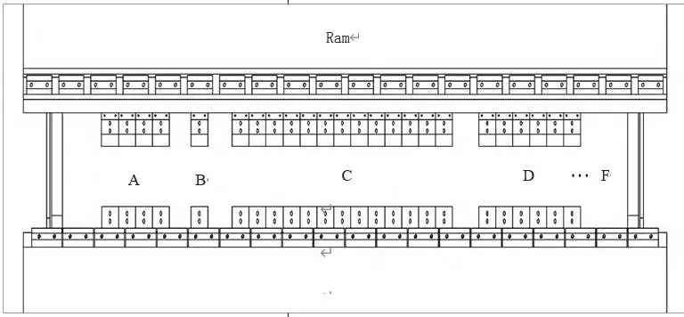
그림 2: Tooling Installation Diagram on the Press Brake
Segmented tooling reduces manual setup requirements and improves production flexibility.
3.2 Automatic Tooling Change Process
When a tooling replacement command is received, the press brake ram moves to the preset position and releases the existing tooling.
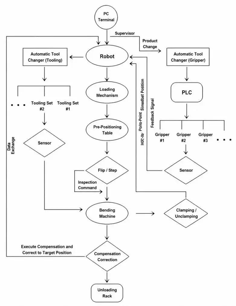
그림 3: Flowchart of the robotic arm bending unit's operation process
The robot moves along the external track axis to the tooling area. The tool-changing gripper engages the pneumatic lock, dislodges the tooling, and places it onto the storage subsystem (see Figure 4).
Thereafter, the required tooling configuration is automatically collected and assembled, eliminating manual effort. This results in a reduction of the setup time and an increase in productivity.
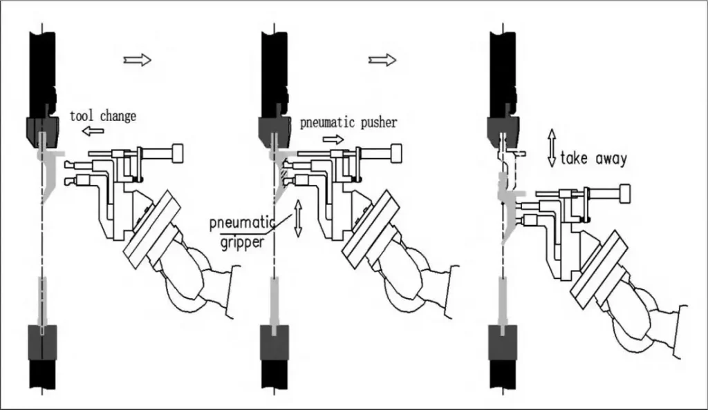
그림 4: Tooling Change Process Diagram
3.3 Tooling Storage System Management
3.3.1 Mechanical Structure of the Tooling Storage System
The tooling storage system integrates mechanical storage and tooling management systems.
The system consists of a welded steel frame that has multiple levels of guide rails. Segmented tooling is stored with the use of spacing blocks. It is capable of holding WILA-standard interface tooling of segment lengths of 20 mm to 100 mm and of a maximum exchange weight of about 15 kg.
The system is capable of storing the following tooling:
• 30° sharp tooling
• 88° gooseneck tooling
• 80° straight tooling
• V8, V20, and V40 lower dies
Tooling complements of diverse configurations are available and can be tailored based on the specific needs of production (see Figure 5).
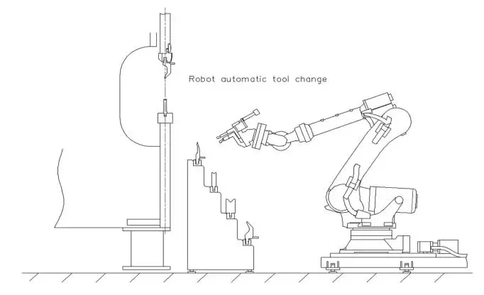
그림 5: Tooling Storage System Diagram
3.3.2 Tooling Management Software Application
The tooling management software provides a visual interface for monitoring tooling status and storage information.
The system displays:
• Tooling position
• Tool availability
• Upper and lower tooling areas
• Current tooling configuration
New tooling data can be added during production adjustments. DXF files can be imported, and existing tooling graphics can be modified, recognized, and stored. Customized tooling areas can also be managed within the system.
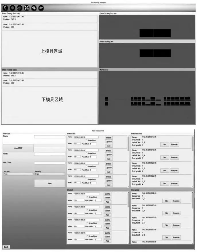
그림 6: Tooling Management Software Interface
3.4 Practical Application: Workpiece-Tooling Matching
A typical application involves 2 mm aluminum-zinc coated steel sheets used in medium and high-voltage electrical cabinets. The procedure involves three primary operations: 30° bending, flattening, and a secondary bending operation.
In traditional systems, tooling replacement requires a manual process, which not only lengthens the setup process, but also creates variability in the process.
The automatic tooling change system allows multiple tooling combinations to be configured on one press brake. This allows for rapid adjustments to accommodate different forming requirements and component complexity (Refer to Figure 7).
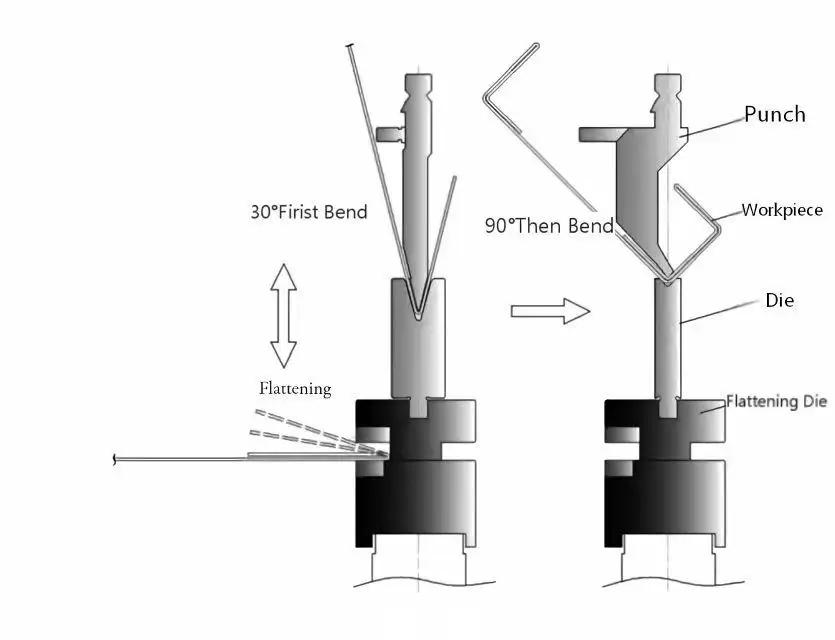
그림 7: Workpiece and Tooling Matching Diagram
4.Automatic Gripper Change System
4.1 Workpiece Gripper Characterization
For mixed-product manufacturing, automated gripper storage systems for robotic bending cells can be implemented.
In this flexible gripper library (see Figure 8), a gripper is mounted on a tool-side coupling and a robot-side coupling is mounted on the A6 axis.
The robot selects the appropriate gripper based on:
• Workpiece geometry
• Material properties
• Sheet size
• Requirements for the handling
Quick-change couplings make it easy to automatically change grippers.
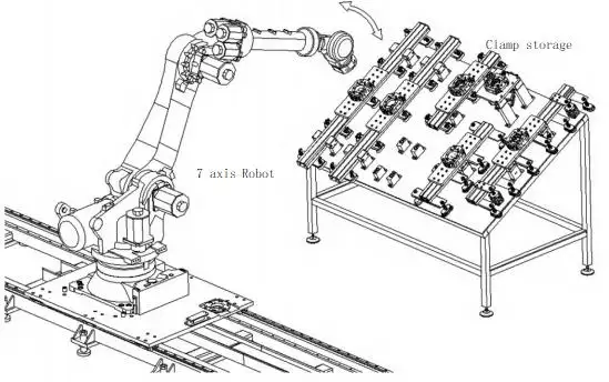
그림 8: Gripper Storage System Diagram
4.2 Gripper Change Method
To achieve a different workpiece with a different gripping requirement, the robot automatically goes back to the storage system, drops the gripper, and attaches the new gripper via the quick coupling system.
This enables the production of mixed-product robotic bending.
4.3 Gripping of Common Workpieces
Robotic bending of sheets made of high strength and thick steel involves high challenges of product handling.
During forming, elastic deformation and bending forces may create pulling forces between the workpiece and robot coordinates, resulting in:
• Workpiece displacement
• Gripper deformation
• Positioning errors
• Robot arm stress
예를 들어, a 4 mm Q420B steel workpiece bent to 90° can achieve approximately 90° ±30′ accuracy under suitable process conditions according to GB/T 33644-2017 requirements.
To reduce deformation effects, a buffer-equipped gripper design is introduced.
4.4 Buffer-Equipped Gripper Technical Parameters
Traditional grippers using vacuum or magnetic solutions have limitations:
• Vacuum cups are unsuitable for perforated sheets or narrow strips.
• Magnetic grippers cannot handle stainless steel and aluminum effectively.
A hybrid buffer gripper combining vacuum suction and pneumatic clamping improves adaptability.
표 1: Vacuum Suction Cup Selection Parameters
| Suction Force / N | Lateral Force / N | Vacuum / MPa | Vacuum Inner Diameter / mm | Connection Thread |
| 140–217 | 110–181 | -0.06 | 4–6 | G3/8-IG |
표 2: Buffer Spring Load Parameters
| Spring Rate / (N/mm) | Solid Length / mm | Helix Direction | Load / N | Compression |
| 35 | 15 | Right-hand | 421 | 매체 |
표 3: Parallel Gripper Cylinder Parameters
| Stroke / mm | 구동 시스템 | Operating Mode | Drive Structure | Gripping Force / N |
| 8 | Pneumatic | Double-acting | Wedge drive | 1000 |
The buffer mechanism uses a pivot structure and spring compensation to absorb bending displacement. The robot can complete gripping, 굽히는, 재배치, and unloading operations with improved stability (Figure 9).

Figure 9: Buffer-Equipped Gripper Diagram
For sheet materials less than 2 mm, including carbon steel, SPCC, stainless steel 304, 그리고 알루미늄도, the elasticity and some suction cup design can be used to handle normal elastic deformation.
5. Is a Robotic Press Brake Cell Worth the Investment?
Investing in robotic press brake cells is a major production decision for many sheet metal manufacturers.
일반적으로, robotic press brake cells are more expensive than traditional CNC press brakes. In addition to the press brake, a robotic press brake cell system could consist of an industrial robot, automated loading and unloading, an auto tool change system, intelligent grippers, safety equipment, and control software.
그럼에도 불구하고, the cost of a robotic press brake cell is only part of the equation. Manufacturers investing in these robotic press brake cells should evaluate the economic worth based on long-term advantages of the system that include:
• Decreased labor costs
• Increased production efficiency
• Improved product consistency
• Decreased changeover times
• Decreased material waste
• Increased manufacturing flexibility
• Enhanced smart manufacturing capabilities
As more manufacturing operations adopt smart manufacturing principles, manufacturers are increasingly focused on productivity to create flexible, data-driven manufacturing systems.
6. Situations That Favor Robotic Press Brake Cells
Not every production environment suits the automation of a robotic press brake.
The decision to invest in a robotic press brake cell considers the following factors:
• Type of product
• Volume of production
• Size and weight of parts
• Variation of products
• Cost of labor
• Availability of skilled workers
• Frequency of changeovers
• Plans for future production
Robotic press brake cells work best in the following scenarios.
대량 생산
Production of large quantities of the same parts over a long period suits the use of a robotic cell to keep a consistent production cycle and limit variation caused by manual interference. This advantage is multiplied if the robotic cell is intended to operate over multiple shifts or, even better, during long periods of unattended production.
Heavy and Large Parts
Some large and heavy sheet metal parts such as door panels, parts for electrical cabinets, and parts for construction machinery may be cumbersome to manually lift and position. A robotic system can handle and lift these parts with consistently less physical workload and risk of injury to workers.
When designing the system, careful consideration must be given to the robot's payload and reach, the design of the gripper, and the deflection of the part.
Many Different Products
The use of a robotic press brake cell is most effectively designed for high production systems when used in conjunction with automatic tool change systems (항공관제), automatic gripper change systems, 오프라인 프로그램.
Labor Shortages or High Labor Costs
Robotic automation may offer better long-term financial solutions where labor is either very expensive or where trained press brake operators are hard to find.
With automation, you lessen the reliance on the skills of individual operators, and you are able to manage the production capacity of your plant more reliably.
7. How to Analyze the ROI of a Robotic Press Brake Cell
The time it takes to get a return on a robotic press brake cell is impacted by many operational and financial factors, 같은:
• Cost of labor
• Volume of parts produced in a year
• Number of shifts per day
• Utilization of the equipment
• Complexity of the workpiece
• How often the products are changed
• How much scrap and rework are done
• Costs associated with training and maintaining the equipment
• Cost of programming and setup
• How long you expect the system to be in service
• From the following angles, manufacturers are able to analyze the potential return.
8. Beyond the Hard Costs: Smart Manufacturing Capabilities
The robotic press brake cell has the ability to be production equipment and an important piece of the automated smart factory.
The press brake cell can be integrated with:
• Sensor technology
• Manufacturing execution systems (MES)
• Enterprise resource planning (ERP) 시스템
• Quality management systems
• Production scheduling software
• Equipment monitoring systems
This integration can facilitate Industry 4.0 concepts such as:
• Automated data collection for production
• Real-time monitoring of equipment
• Work orders
• Production traceability
• Energy analysis
• Quality reporting
• Preventive maintenance
• Intelligent scheduling
Orders and tasks can flow from the ERP or MES to the robotic cell. In turn the cell can provide status, quantity, 경고, and quality information to the management systems.
This helps to create a more integrated manufacturing system.
It is anticipated that upcoming robotic bending systems will be more flexible and intelligent, with a greater ability to self-adapt and lessen their reliance on programming and manual intervention.
Manufacturers can expect to see a return on investment when integrating a robotic press brake cell. This is even more likely with the ongoing labor shortages and the expense of press brake operations. This cell can become an integral part of an automated and planned production system.
결론
The sheet metal industry is challenged by the increasing costs of production, skilled labor shortages, and the demand for superior quality.
Robotic press brake cells are particularly beneficial for:
• High volume production
• Multiple bend operations
• Large pieces
• High mix low volume
By reducing the manual processes, productivity of the manufacturing operation is enhanced. This allows the skilled worker to concentrate on the process improvement and value adding activities.
The combination of advanced Artificial Intelligence, industrial communication, and smart factory systems offers the potential for total digital integration of the sheet metal manufacturing process. The robotic bending system, based on edge computing, creates the opportunity for local production data to be processed and, in the future, be integrated with centralized manufacturing systems.
As flexible automation and intelligent manufacturing technologies continue to develop, robotic press brake cells will become an important solution for achieving smarter, more efficient, and more adaptable sheet metal fabrication.
JS 라고스와 파트너 for intelligent robotic bending solutions and advanced sheet metal automation.
Planning a robotic bending project? Share your part drawings, 자료, thickness and production requirements with our team to find a suitable custom robotic bending system.
자주 묻는 질문
질문 1. Can press brake cells with robotics perform automatic tool changes?
확실히 그렇습니다. Automatic tool change systems will diminish set up times and enhance production capability.
질문 2. What advantages do robotic press brake cells have?
Robotic press brake cells have the advantage of better overall productivity, decreased requirement for labor, and uniform bending accuracy.
질문 3. What markets utilize robotic press brake cells?
Robotic press brake cells are found in the automotive market, 전기 캐비닛, construction machinery and industrial equipment.
Q4. Can robotic press brake cells perform small batch production?
절대로. Small batch production of many different products can be accomplished with the use of flexible tooling and gripping systems.
질문 5. What are the limitations of robotic press brake cells in regard to material?
Robotic press brake cells are capable of processing many different types of materials including many sheet metals as well as aluminum, stainless and carbon steel.
질문 6. How much does a robotic press brake cell cost?
Different robotic requirements correspond to different costs. While the basic model is highly affordable, customized features—such as MES integration, automatic angle measurement, or Automatic Tool Changing (항공관제)—will vary a lot in price depending on your specifications. Please feel free to send an inquiry to JS Ragos to get our best competitive offer!
Q7. Can one robot operate multiple press brakes?
네, we can put two press brakes in a line and use a very long ground rail to connect two press brakes
질문 8. What robot brands are supported?
파눅스, 무화과, 누구, 야스카와, and Estun
Q9. Can robotic bending cells bend stainless steel?
네, as long as we choose suitable robot and press brake model based on product drawings
Q10. Is offline programming necessary?
아니요, the offline software can save a lot of time the operator porgrams if they have new products to be programmed, but it is not necessary, manual program also can work.